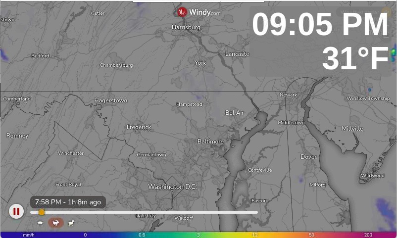
So I was sad that our favorite weather display, that we keep right under our living room TV, stopped displaying the radar. This project was an awesome Raspberry Pi display project and we loved it for a number of years. But, it has been without developer support for a while, and rainviewer changed the API that you use to get the radar. This meant many displays were just static maps now. I tried to roll a dashboard view with my home assistant, but there are too many issues with aligning cards and getting this to work from one screen to another (RPI 7″ Touch Screen). Then I stumbled across Windy.com. They let you create an embeded iframe through their website.
So I wasn’t up for trying to learn how to code modern webpages. I used to do SGML if anyone remembers what that was. So I went to ChatGPT and asked it to build me an HTML doc with a Clock and Temperature overlay to mimic the Pi Weather Station main elements. It did an amazing job.
So if you have a PI you want to display this on, there are a few things I figured out.
Go to windy.com and generate your map. I chose to use the weather radar and set it to 800×500 for my PI display. Then copy the embeded code.
Next, create an empty HTML doc and paste the following code into it:
<!DOCTYPE html> <html lang="en"> <head> <meta charset="UTF-8"> <meta name="viewport" content="width=device-width, initial-scale=1.0"> <title>Clock + Live Temperature</title> <style> html, body { margin: 0; padding: 0; height: 100%; overflow: hidden; font-family: Arial, sans-serif; background: #000; } .iframe-container { position: relative; width: 100%; height: 100%; } iframe { width: 100%; height: 100%; border: none; } .info-box { position: absolute; top: 20px; right: 20px; background: rgba(128, 128, 128, 0.85); padding: 10px 10px; border-radius: 6px; text-align: right; color: #fff; z-index: 1000; } .time { font-size: 3rem; font-weight: bold; margin: 0; line-height: 1; } .temp { font-size: 3rem; font-weight: bold; margin-top: 5px; line-height: 1; } </style> </head> <body> <div class="iframe-container"> <!-- INSERT YOUR IFRAME LINK HERE --> <div class="info-box"> <div class="time" id="clock">--:--:--</div> <div class="temp" id="temperature">Loading...</div> </div> </div> <script> function updateClock() { const now = new Date(); let hours = now.getHours(); const minutes = now.getMinutes().toString().padStart(2, '0'); const seconds = now.getSeconds().toString().padStart(2, '0'); const ampm = hours >= 12 ? 'PM' : 'AM'; hours = hours % 12; hours = hours ? hours : 12; // Convert 0 to 12 hours = hours.toString().padStart(2, '0'); document.getElementById('clock').textContent = `${hours}:${minutes} ${ampm}`; } async function updateTemperature() { try { const lat = ; const lon = ; const response = await fetch( `https://api.open-meteo.com/v1/forecast?latitude=${lat}&longitude=${lon}¤t_weather=true&temperature_unit=fahrenheit` ); const data = await response.json(); const temp = Math.round(data.current_weather.temperature); document.getElementById('temperature').textContent = `${temp}°F`; } catch (error) { document.getElementById('temperature').textContent = "Temp unavailable"; } } updateClock(); setInterval(updateClock, 500); updateTemperature(); setInterval(updateTemperature, 600000); </script> </body> </html>
Below where it says <!– INSERT YOUR IFRAME LINK HERE –> paste in your embeded iframe from windy.com and update const lat and const lon values for your location to get temperature. Bonus tip, add &play=1 inside the qoutes at the end of the windy iframe string right after the long and lat. This will auto play the page when it opens.
Mess with the size of the fonts, change the location and padding, you just have to reload the file to see the changes. If anyone is interested, I’ll post the changes I made to my RPI running Trixie to turn the screen on and off and to auto launch this display and open fullscreen without hitting F11 all the time.