Adding LEDs to my Anet A8 Plus with Octopi Control
Posted by Rob On March 21st, 2020
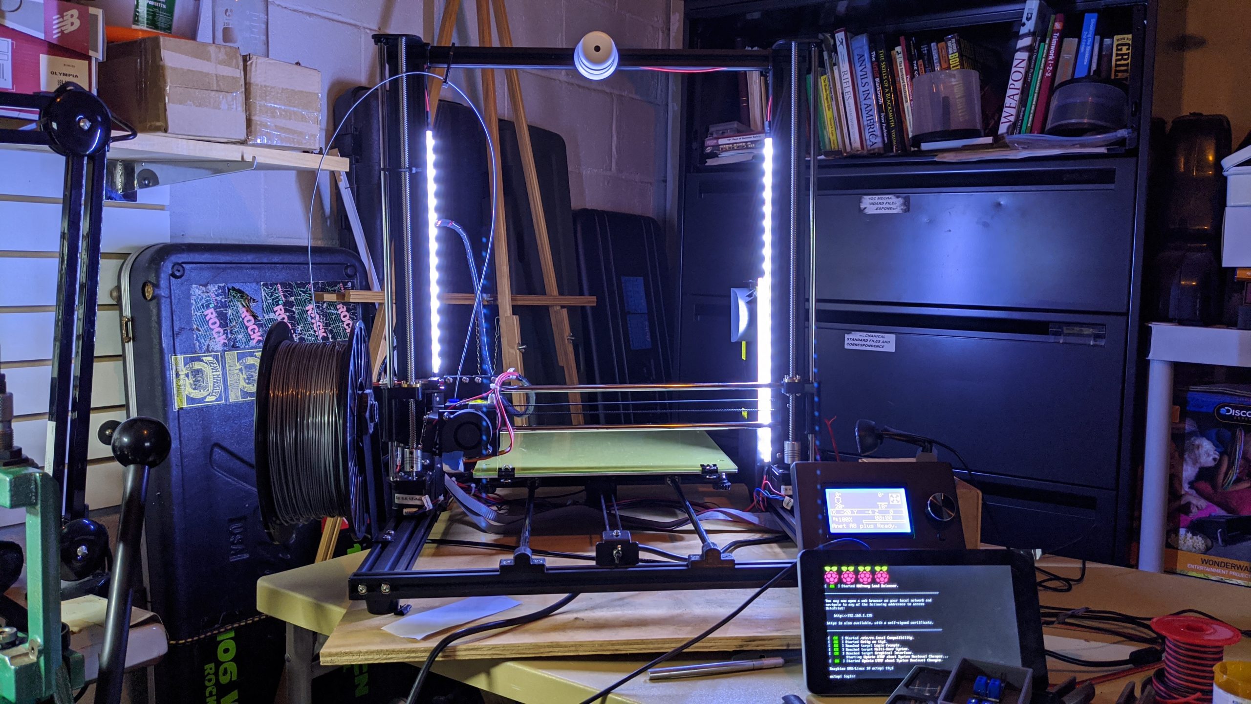
To add dimmable LEDs to my 3d printer, I bought some 24v LEDs strips from Amazon. Along with the strips I bought a high power dual mosfet driver board to be able to control the power going to the LEDs.
The following is the basic wiring diagram of the driver board:

Image by icstation.com
The load is the LED strip and the power comes straight from the 3d printer PSU 24v terminals. the PWM signal that switches the MOSFETs comes from PWM pins on the rpasberry PI. I have the GPIO pins here below:
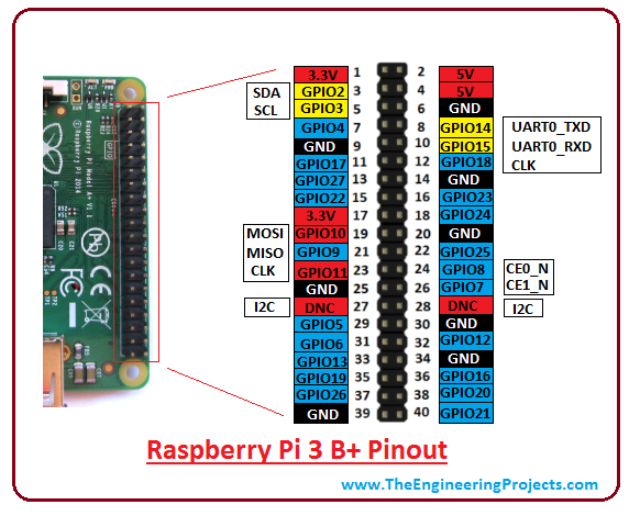
When I built mine I chose to use PINS 32 and 34 as they were the easiest to get to. However any PWM pin is fine as long as you know what it’s called in the software. Here it’s GPIO 12.
Here’s a picture of the PINs on my board:

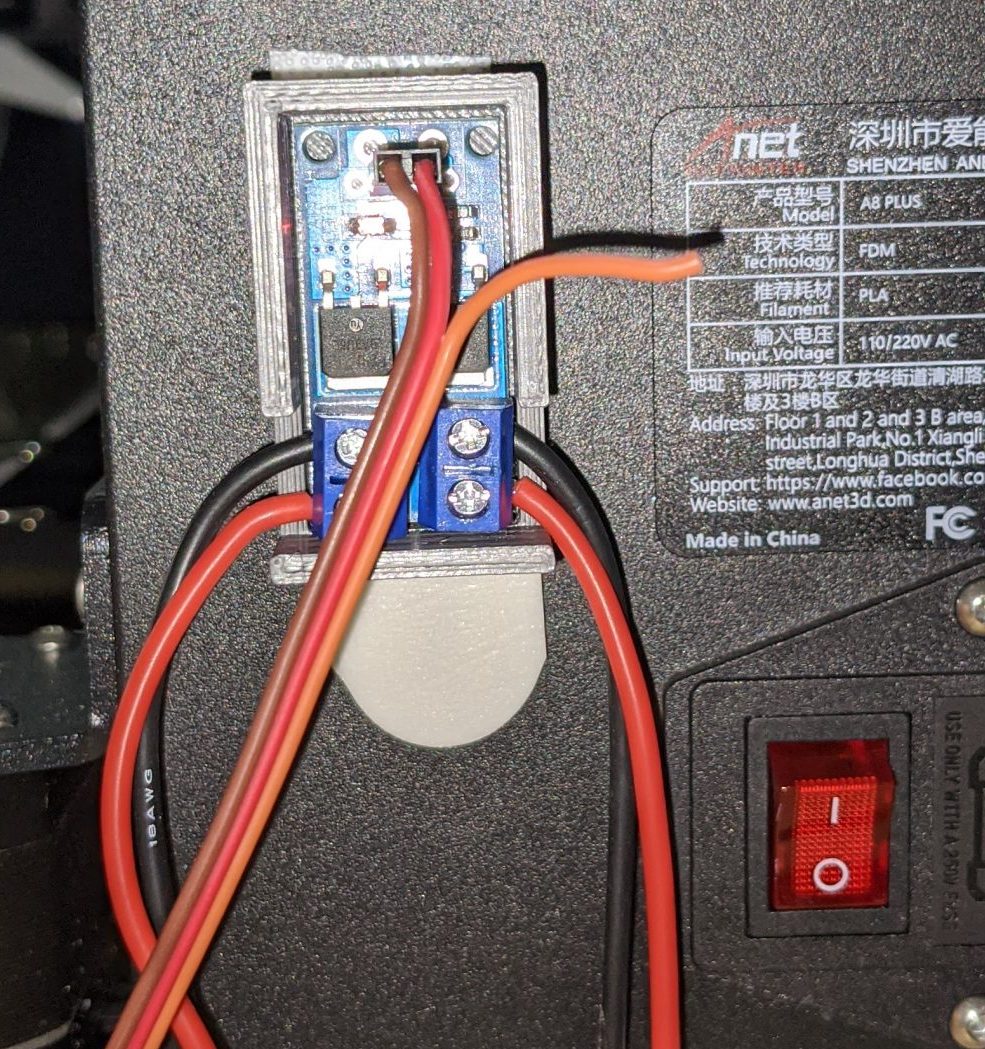
And here’s the other end connected to the MOSFET board:
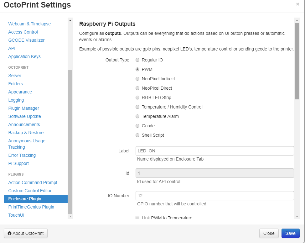
Next was to install plugins in Octopi to be able to control the GPIO and in turn, the LED brightness. Below is a screen shot of the plugins and their configurations. The plugins I used were Enclosure and Custom Control Editor. First setup Enclosure plugin to control the GPIO port as below:
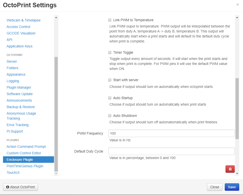
I used 100Hz to prevent flicker of the LEDs. You can try different values based on your preferences.
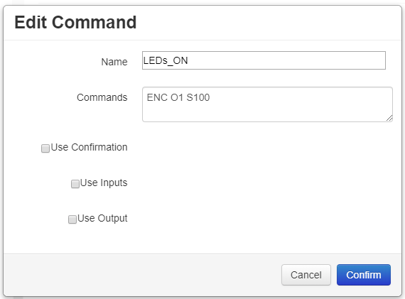
Once the port was defined, you can access it by issuing the gcode command ENC O1 S0 where ENC is for enclosure, O is for the outputs logical number as defined in the previous step, and S is the value in percentage. So S0 is off and S100 is full on.
Next I created buttons to control this from the Octoprint web interface. This uses the Custom Control Editor plugin. This plugin is great for commanding things like go to center of bed etc. Here I created buttons with the command above behind it to control the LEDs:
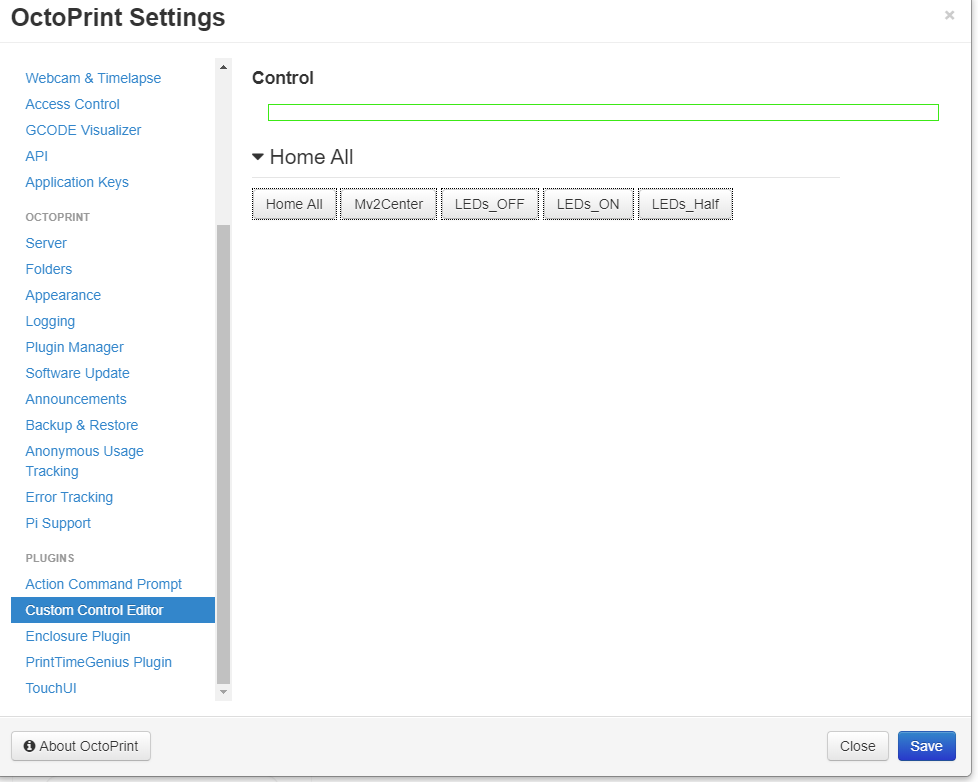
And that’s it!
Home grown DR!
Posted by Rob On October 3rd, 2018
Decided to use an old 2Tb drive for a raspberry pi based backup server. The software is urbackup. It runs on Linux and windows and does file and image backups. The install was easy. I found a rpi shield to attach the drive and a housing to clean the whole thing up.
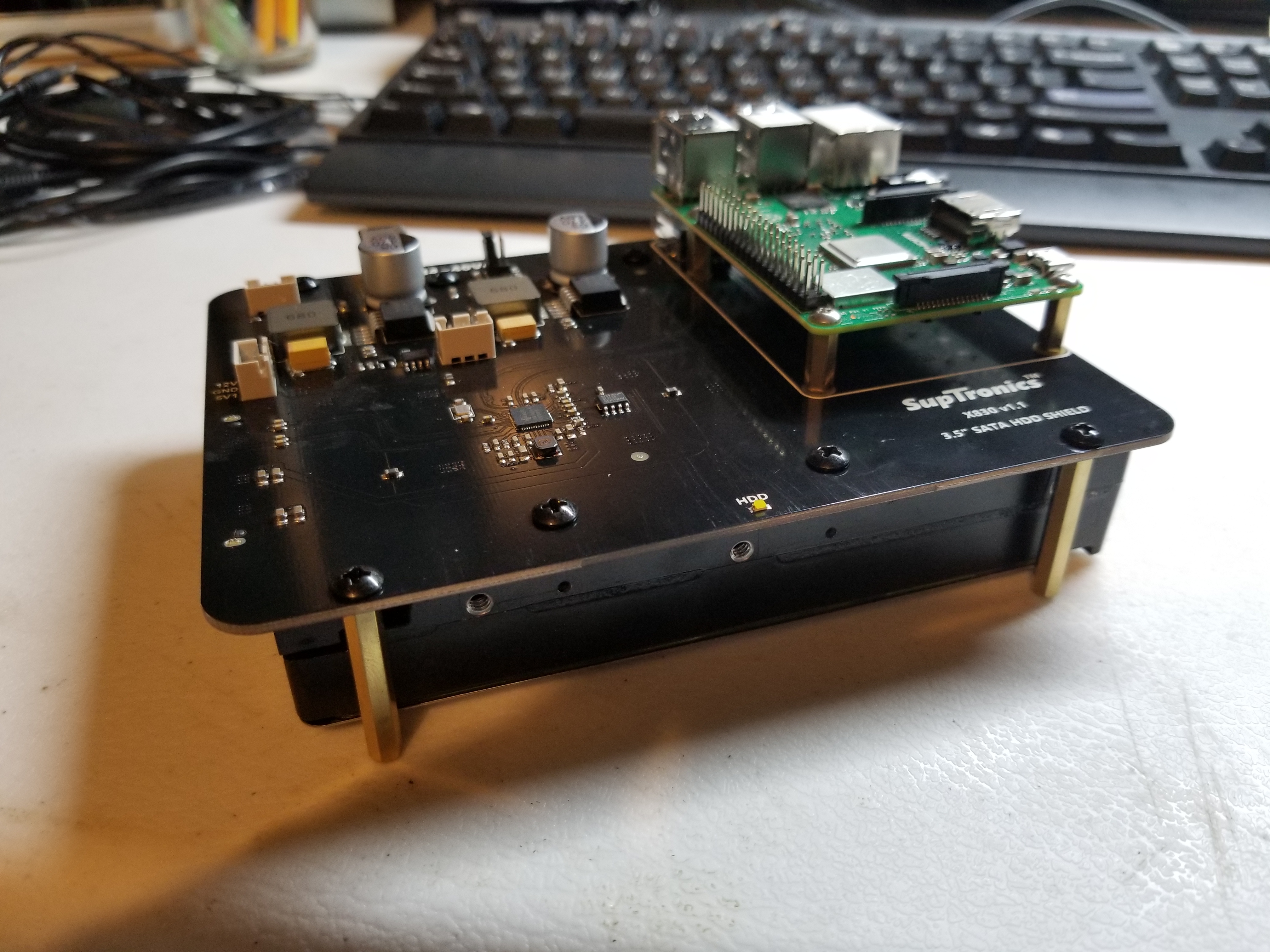
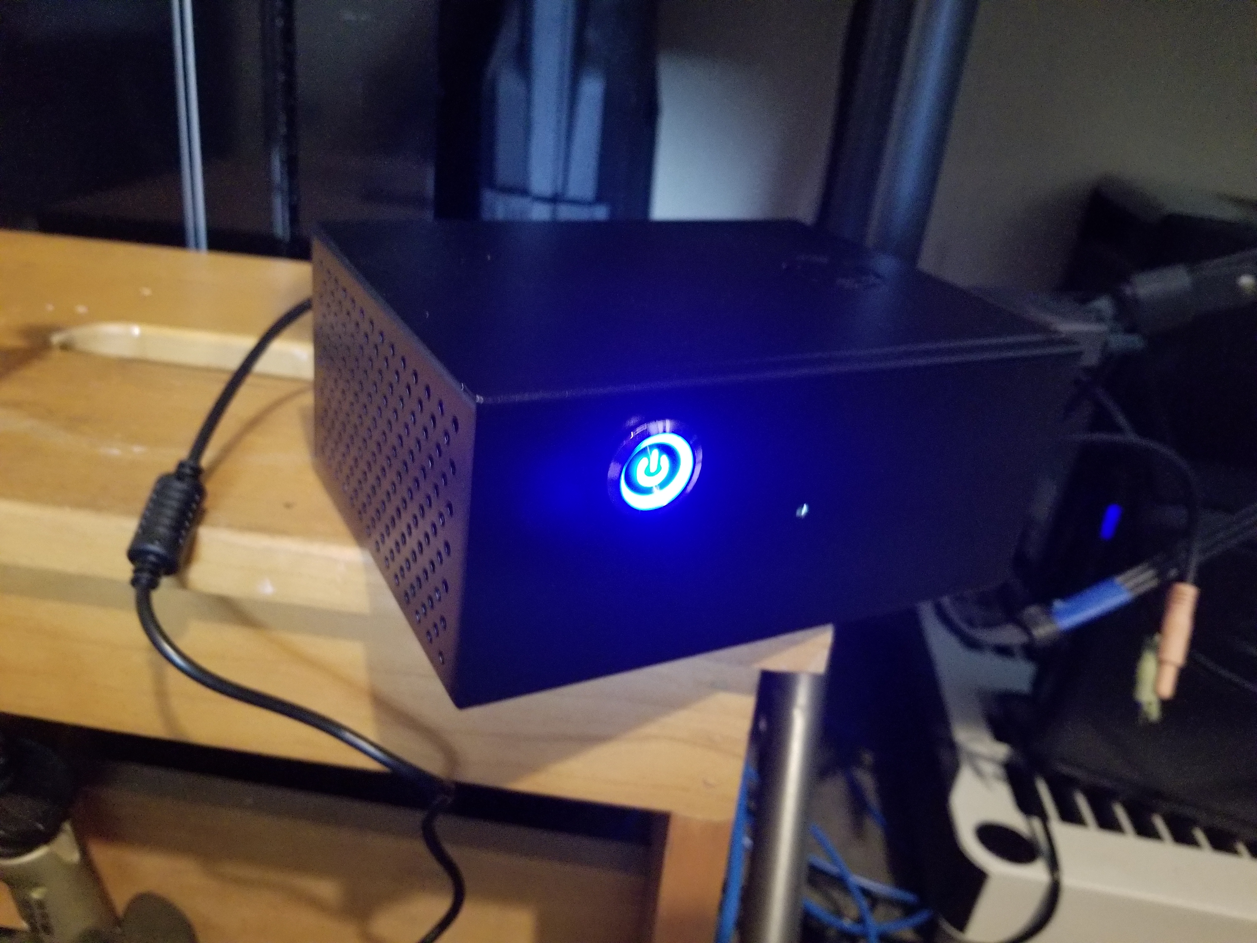
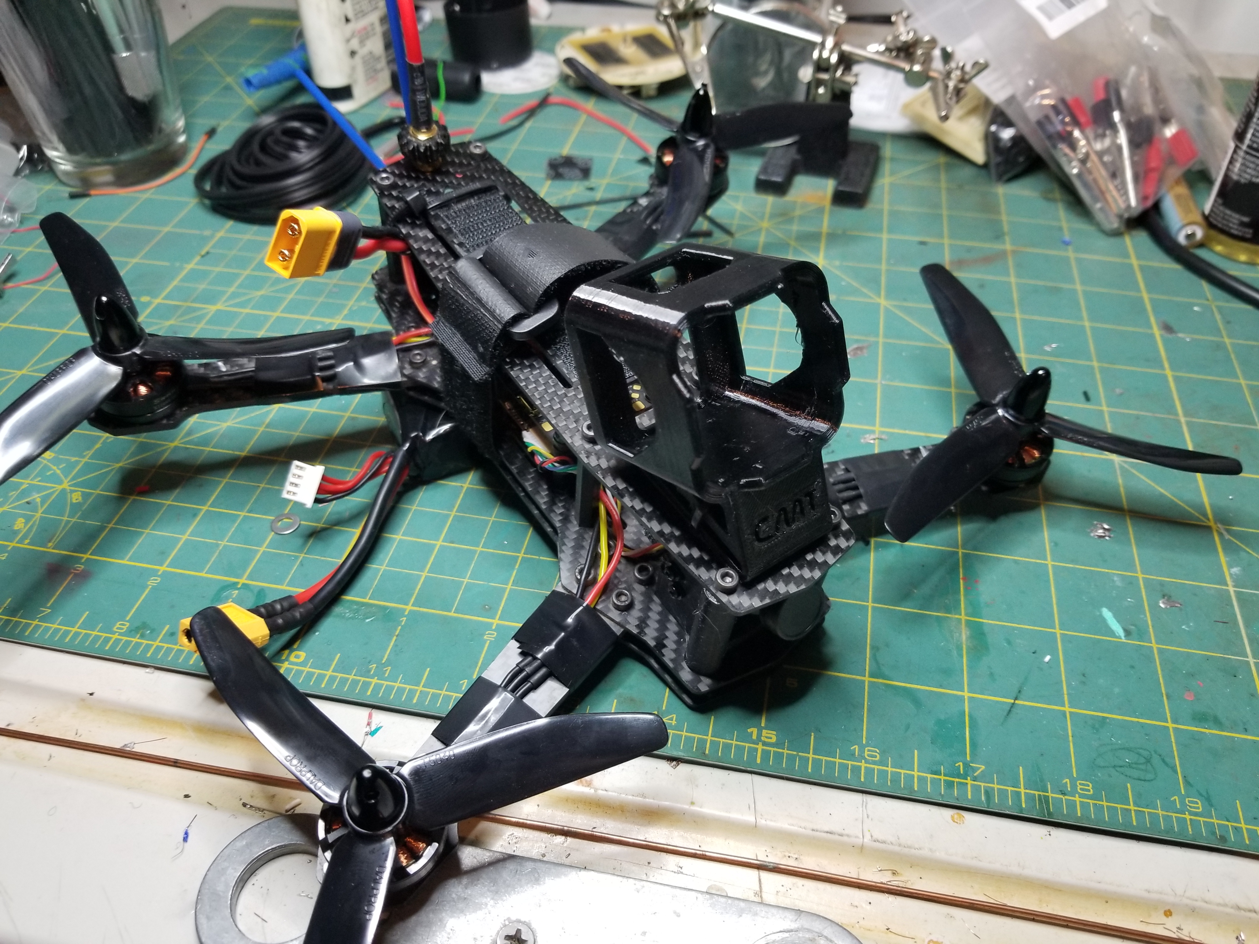
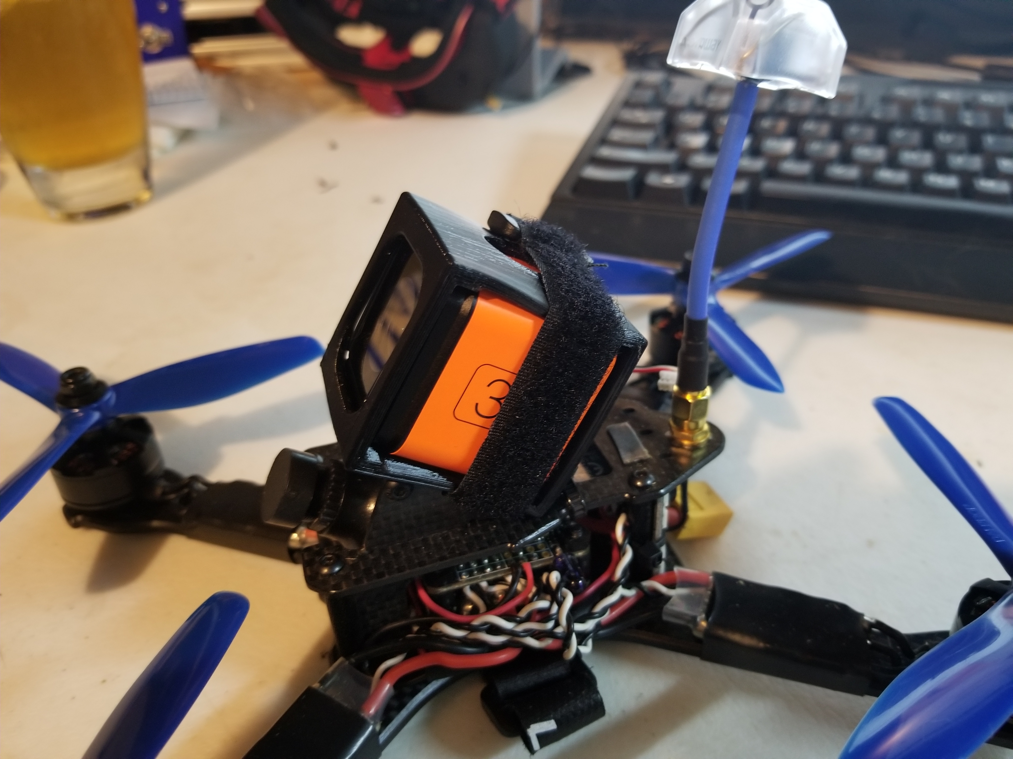
Ready for maiden!
Posted by Rob On August 23rd, 2018
The zmr-250 2.0 is ready for flight testing… Even if I’m not. (Still on crutches)
So many things
Posted by Rob On August 22nd, 2018
Since my last post I have built another quad, bought a babyhawk and am now rebuilding the zmr.
The other quad was a qav-xs. I used a brainfpv re1 and power board. I’ve been unhappy with the way it’s been flying. So that’s when I decided to rebuild the zmr.
The new zmr is using a Josh Bardwell f4 and a dys 4 in 1. The 4 in 1 makes for a nice clean build.
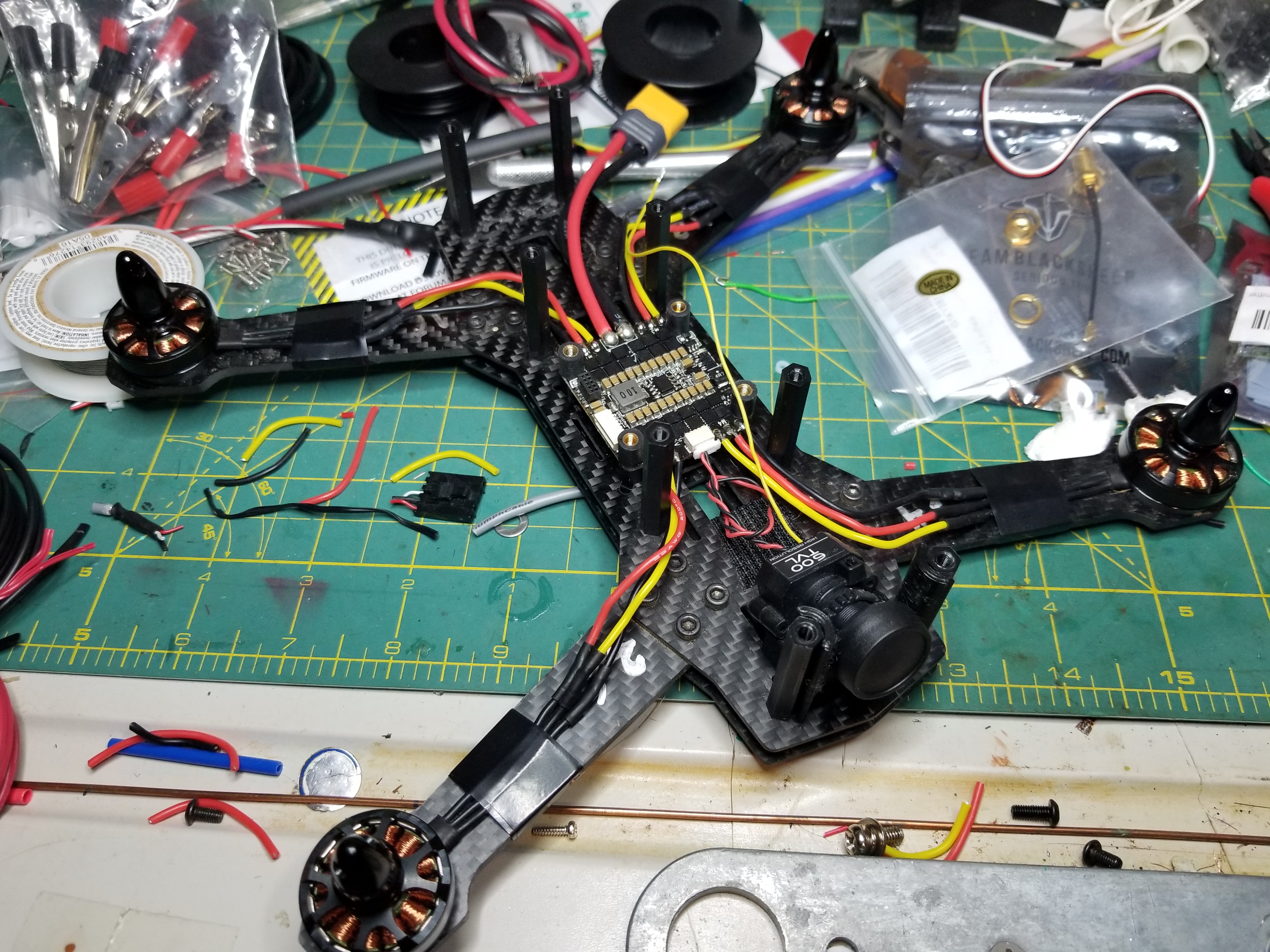
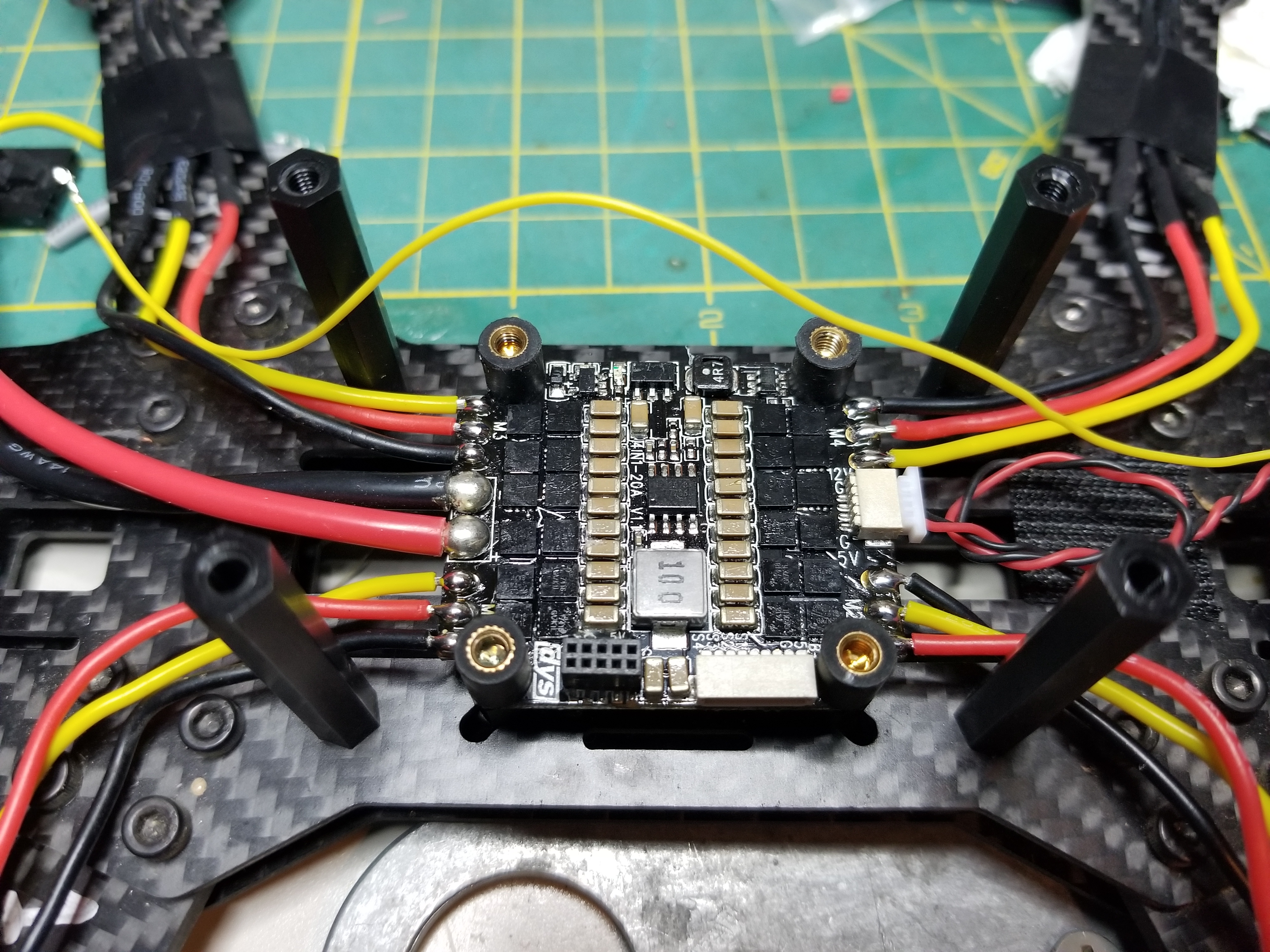
The board connects with a jst cable and that’s all.
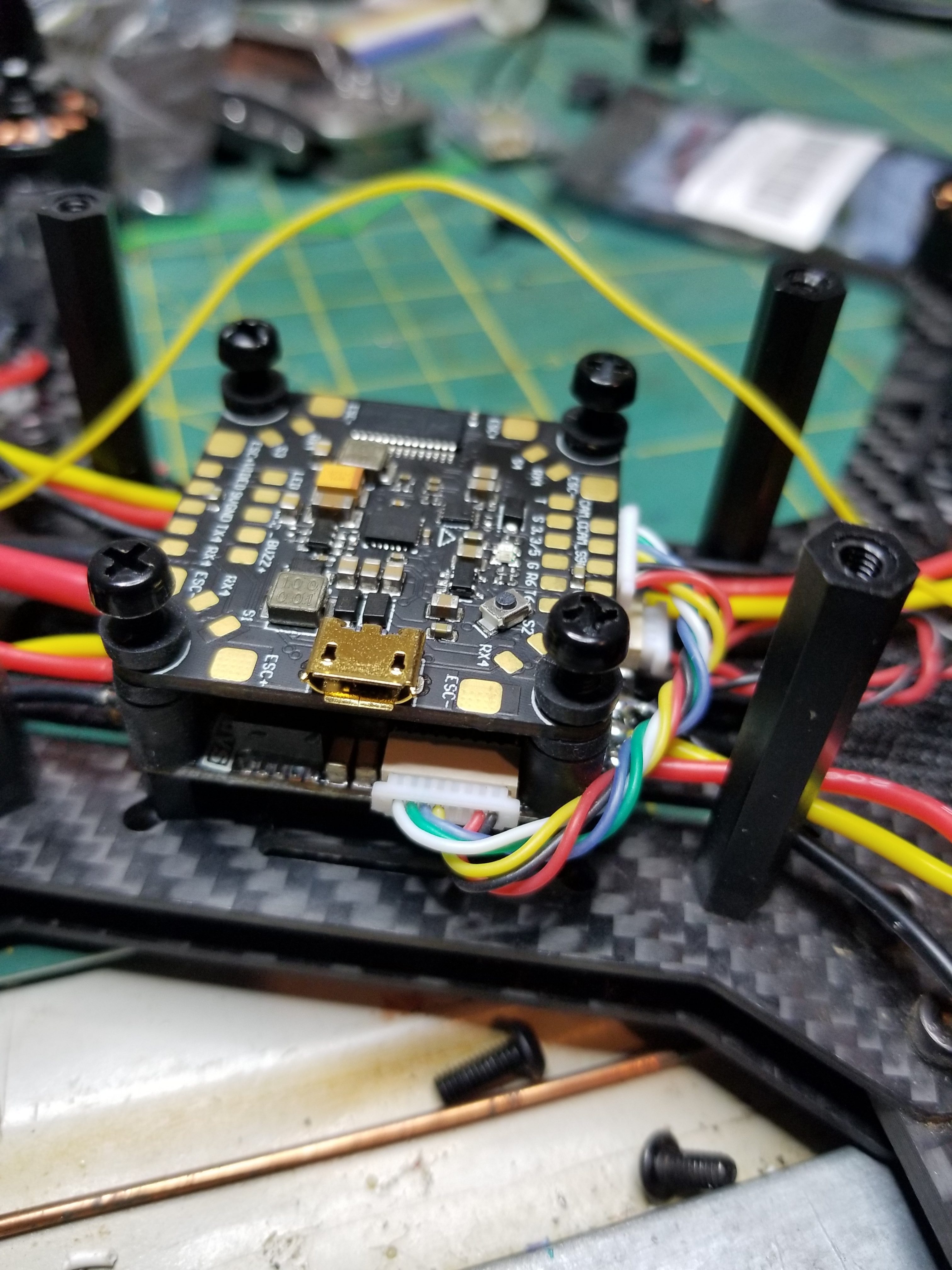
My next task is to connect all the peripherals. Some of the parts I need I’m printing with my new D300VS Delta printer out of my new best friend TPU 😀.
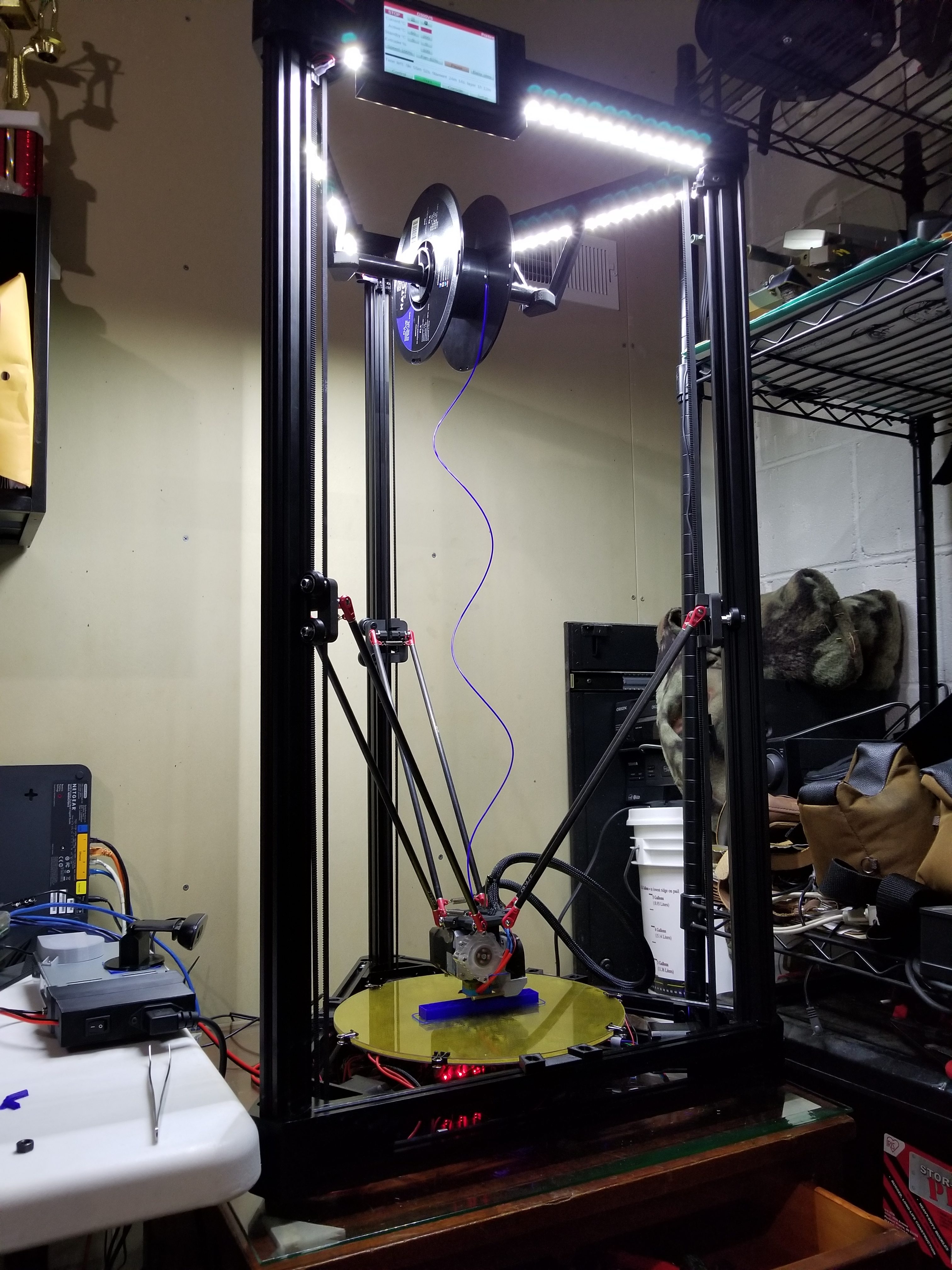
It allows me to make things like this:
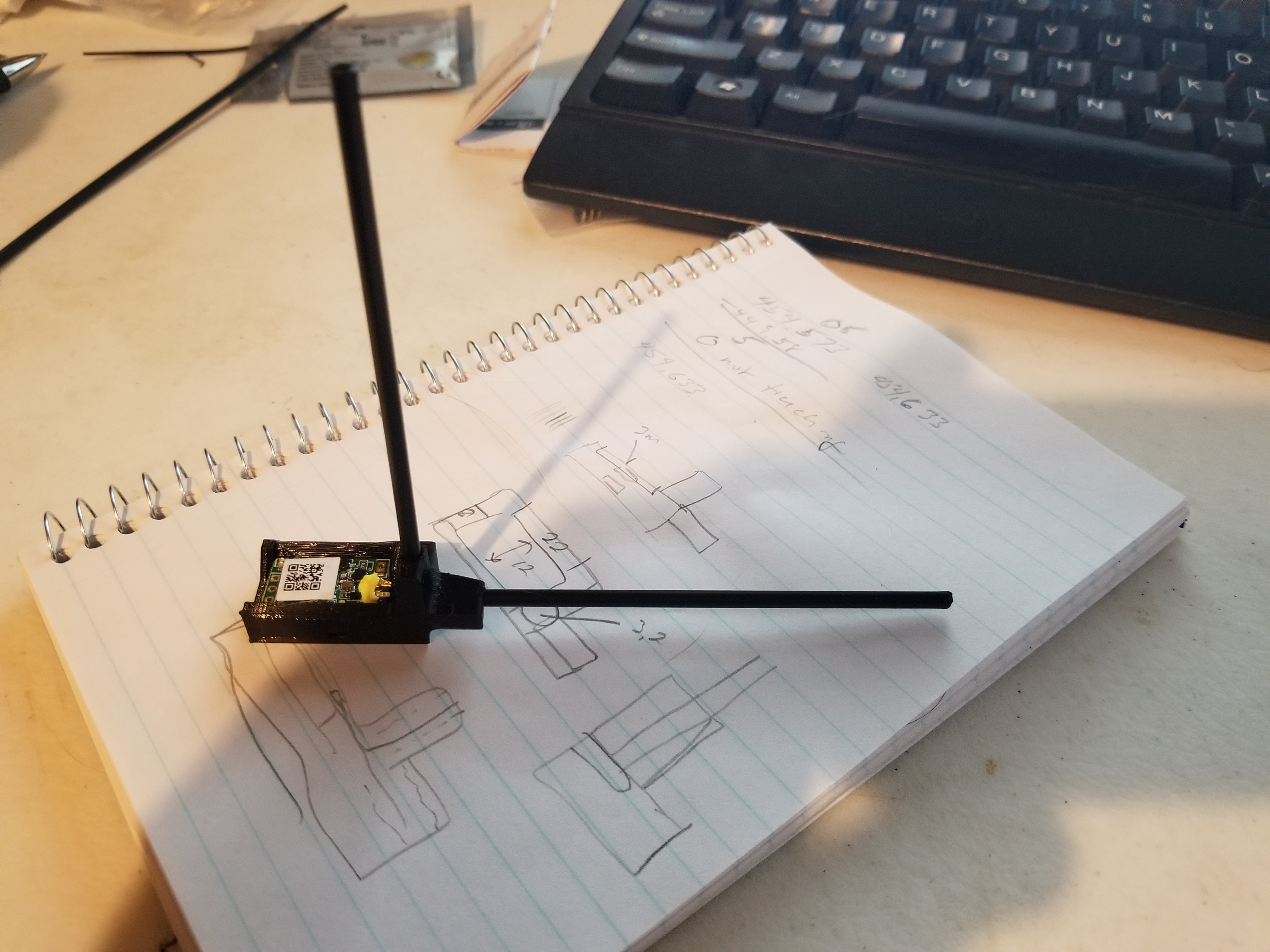
And this:
ZMR250 Update!
Posted by Rob On August 20th, 2016
Finally got out to fly. After spending way too much time trying to get Autotune to work and failing. I was getting oscillations caused by a D gain that was too high, I finally decided to tune from scratch. Got it flying pretty well. In the meantime I had been practicing on FPVFreerider which made a massive difference. Here’s my first and second FPV sessions:
Smallest Soldering I’ve Ever Done
Posted by Rob On February 22nd, 2016
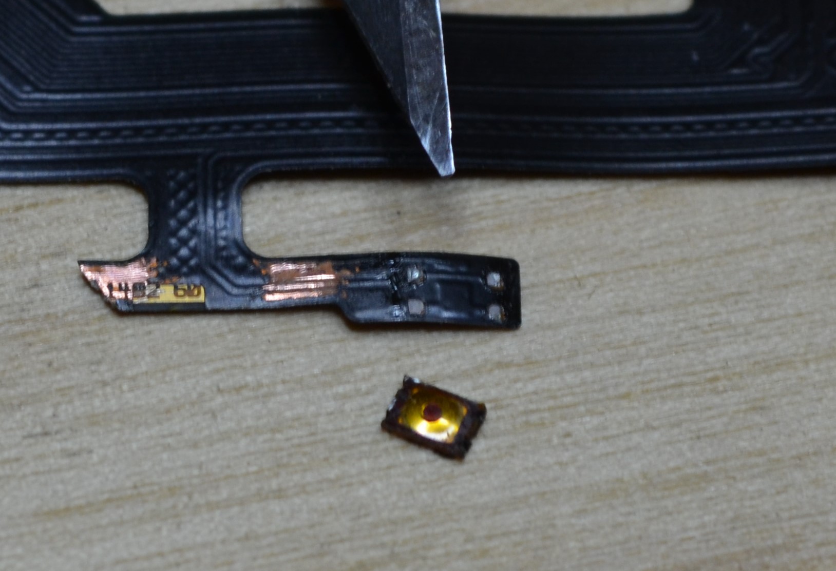
While taking my phone apart to repair a broken usb port, I accidentally damaged my up volume button. I cut right through it with the spudging tool while going down the right side of the phone. Since it was only the vol up button, I was able to use the phone by pressing the vol down, then dragging the slider back up. I thought I might be able to mend the ribbon cable but that proved to be too difficult as the traces on the ribbon were not accessible. So instead I opted for de-soldering the tactile buttons and soldering them on to the existing phone. (Replacing the whole cable requires separating the screen from the body.)
Here you can see the button that I removed from a new cable purchased from ebay for $6.
Once I had the buttons removed from the spare cable, all I had to do was get the 4 corners to stick to the pads on the phone’s cable.
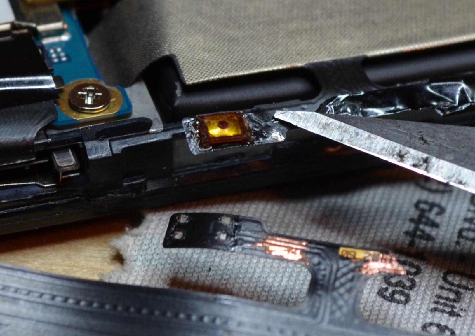
And there ya go! All fixed. The new button is a hair stiffer than the original, but it works fine.
Building a ZMR250 FPV Race quad
Posted by Rob On October 28th, 2015
So after I built a weed whacker of a tricopter, I decided it was way too big to learn on. It’s great for nice smooth Aerial Video flying but doesn’t fit many places when taking off and landing safely.
So after watching a number of videos on FPV Race Quads, I figured I would see how to build one fairly cheaply.
For the build I chose a clone of the Blackout quad, the ZMR250.
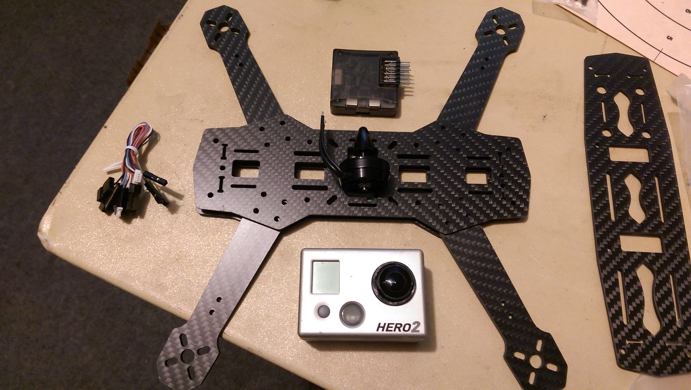
I mocked the whole thing up with masking tape to determine where everything should go to fit nicely.
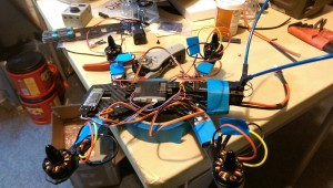
I ordered some 3mm spacers and nylon standoffs for the top plate. The 3mm spacers will allow me to separate the bottom plates by 6mm to allow for my esc wiring. I created a simple PDB with copper clad, then I heat shrink it to protect it from shorting.
There were some challenges. First was that the open pilot cc3d board ($17 from buddy rc) is no longer supported by open pilot. In fact it appears OP has collapsed all together. Thankfully some of the devs went over to Taulabs. I had been looking at a BrainFPV board running Taulabs because it incorporates the OSD on the board. It’s a little pricey at $100 though so I’ll stick with this until I get better.
Once I had the board, I was able to update it to the latest TL software using their GCS. Then I began the setup wizard.
To be able to connect for tuning in the field, I decided to get a HC-05 bluetooth module. This was a little bit of a PITA. To update the BR to 57600 as required by the FC, I had to connect it to an FTDI TTL usb to serial adapter. THen to get into programming mode you have to hold the reset while applying power. This causes a slow blink meaning command mode. I was then able to issue commands through putty like AT+UART=57600,1,0. I also issued a AT+NAME command however this cause it to reboot. It did accept the new name though as ZMR250.
Here are the specs:
ZMR250 frame
SunnySky 2204 2300kv motors
RMRC BLHeli 12A ESC with oneshot and braking
GemFan 5×3 props (to start)
OP CC3D board
HC-05 Bluetooth
3S-1300 45C battery
More to come as time permits!
Update! 1/27/16
I spent a while trying to get TauLabs software to work with the cc3d in that I wanted autotune. There isn’t enough stack room to enable the module and bluetooth, so you have to disable BT telem. Then when you run the autotune, it will fail to reconnect to the GCS to save the settings. This was incredibly frustrating. I tried to run it this way multiple times with the same result. Fortunately, some contributors forked the project for more rapid releases under a fork called DRonin.
The website is http://dronin.org/
So far I’ve installed this successfully on my CC3D. Once installed I was able to enable autotune and run a props off test of the module. Of course the settings were really off the wall but it worked. Another nice feature of the DRonin version is that it saves the values when you disarm as long as you don’t change flight modes. If you change flight modes the settings are reverted. You are not required to connect to the GCS like TauLabs to save the changes. I did test it though, and it did reconnect. So another big plus for DRonin.
Once we get dug out of the snow, I’ll give it a shot and upload the results.
GPS Cat Collar Build
Posted by Rob On February 14th, 2015
This is being added a long time after Leo wore and lost his second GPS collar. One I built myself. Here are pics and a brief description of the build.
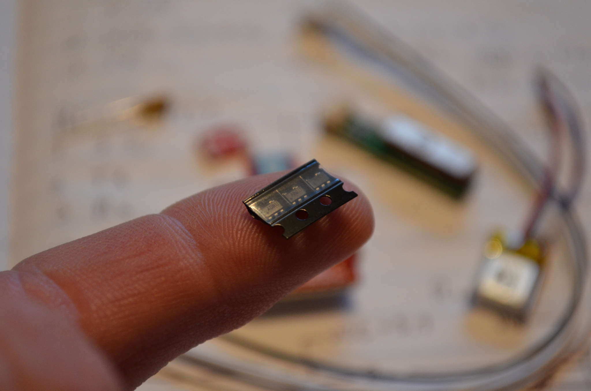
This first pic is of the three major components.
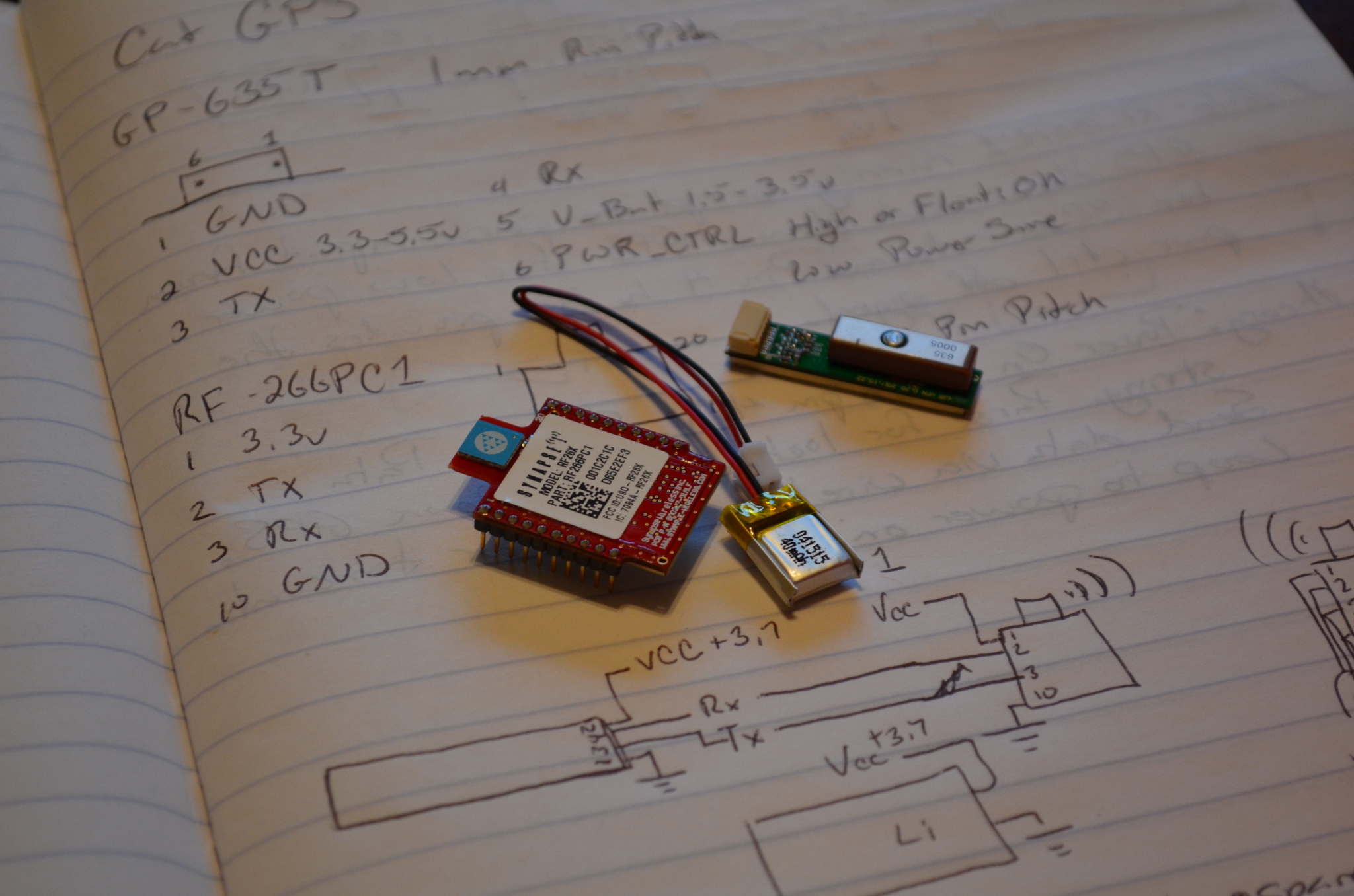
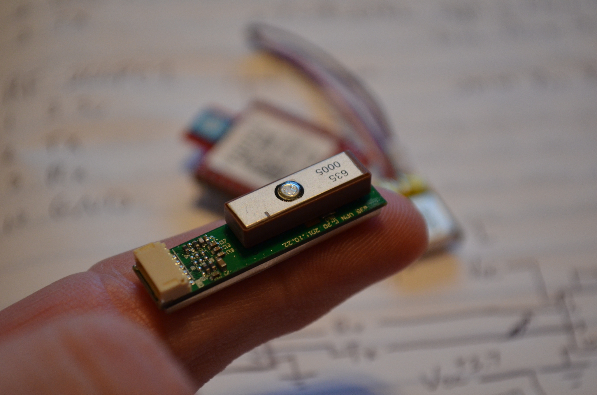
This is the GPS module that the system is based off of.
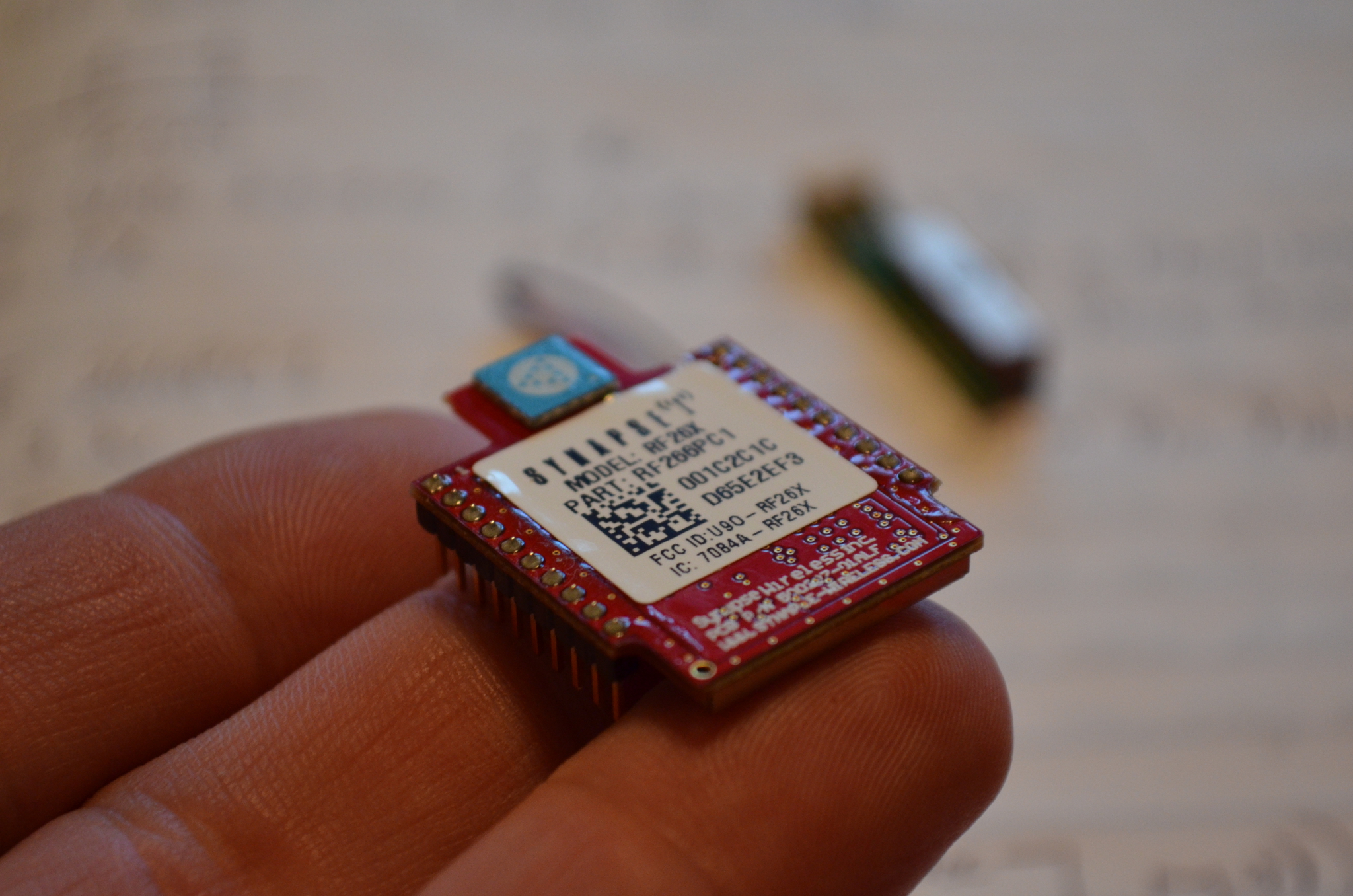
This module is the brain of the collar. It’s a synapse wireless python virtual machine. Basically n SOC. It runs the python code that listens to the GPS module, parses the data and then transmits it back to the house. Once the module gets acknowledged by the house, it puts the GPS in a low power sleep, then sleeps itself and waits 3 minutes.
Below are three buck boost power supply chips. This produces a 3.3v supply from a Lipo battery that powers the whole thing.
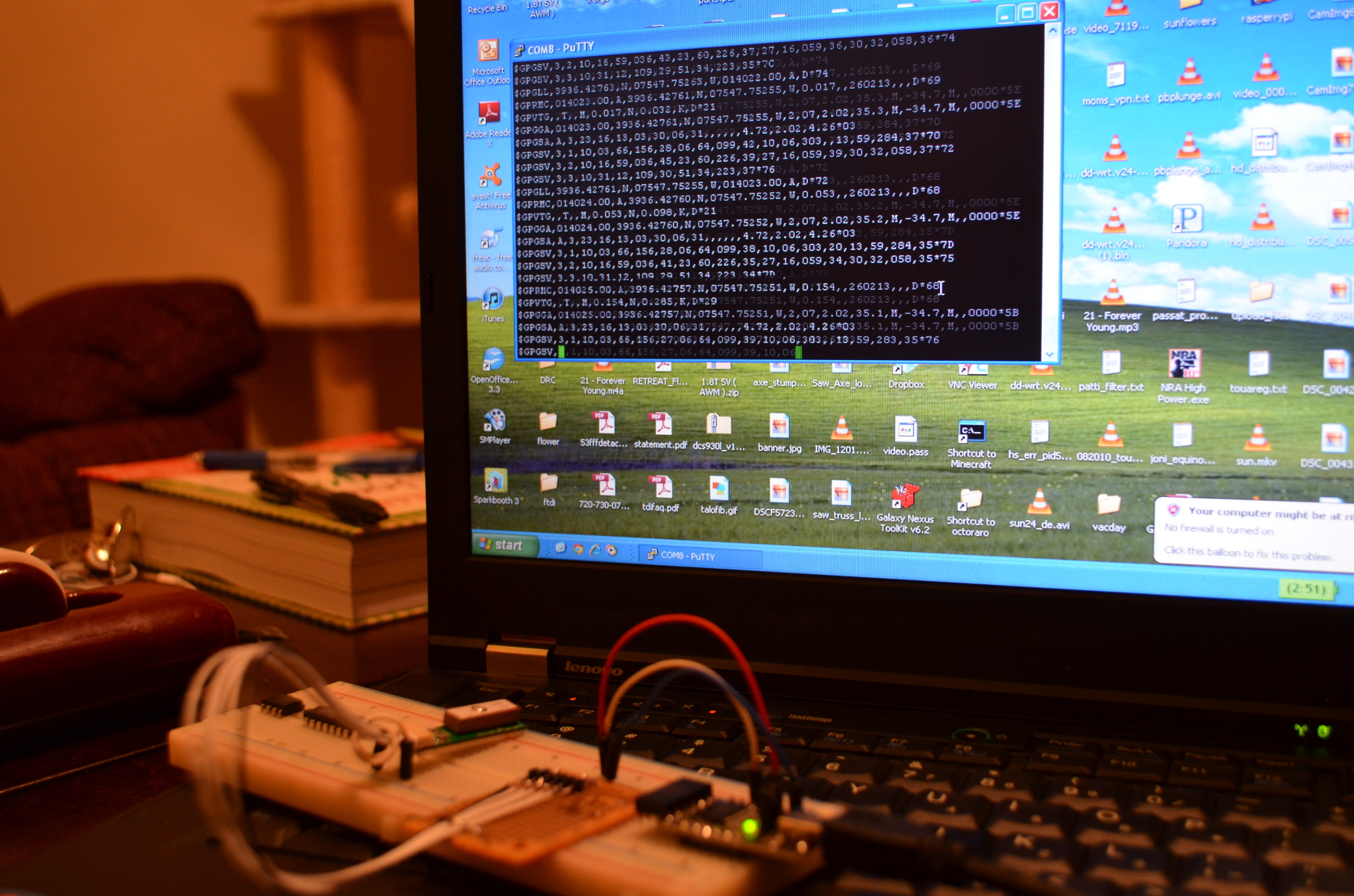
Here is a picture of the actual data stream coming from the GPS in testing. This is what the python codes has to parse to determine the number of satellites and location.
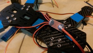
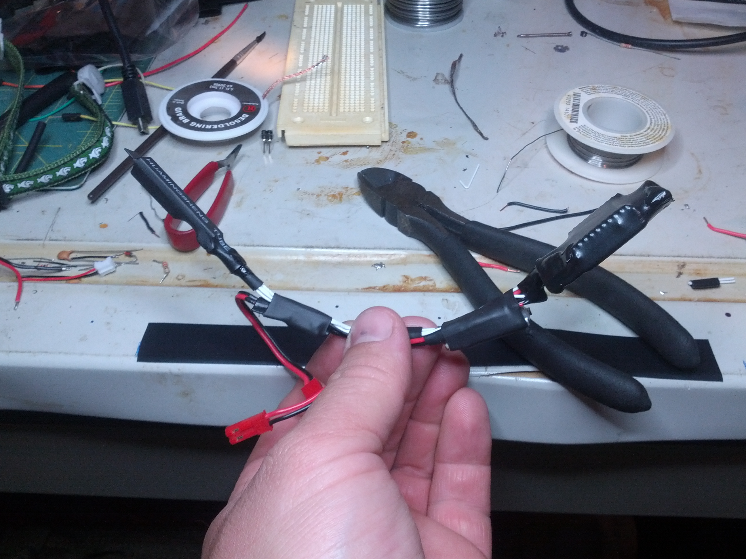
This is the final layout of the collar before waterproofing and wrapping in plastic mesh.
So unfortunately, the last contact was in our yard. Leo came back to the house with cob webs on his face. So he was probably under the garage when he unsnapped the collar 🙁
Time Lapse of neighbors car and grass
Posted by Rob On July 31st, 2014
Our neighbors have not moved their car in almost a year. they also don’t believe in mowing their grass, going outdoors, or cooking food. This was meant to be a time lapse of the car not moving but also caught the last month of not mowing. RANDY!!!! Tell them to mow!!!!
This is my first post!
Posted by Rob On July 17th, 2014
Hopefully I will start to populate this with the projects that I like to tinker with like fixing gopros, gps tracking the cat, and building UAVs. Oh ya and Blacksmithing, welding, motorcycles, microcontrollers, computers…